Product Description
Motor use shaft coupling flex tire coupling with ISO9001
Product Description
♦Description
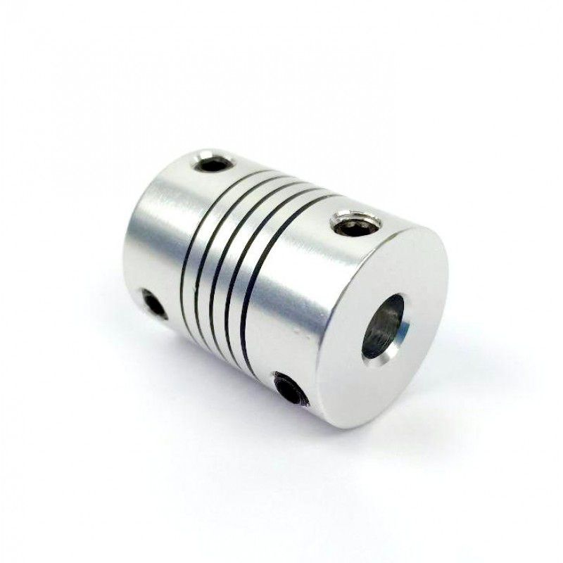
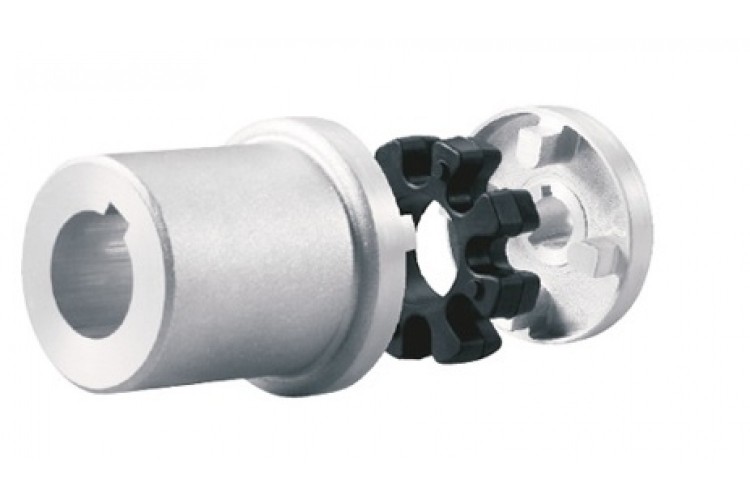
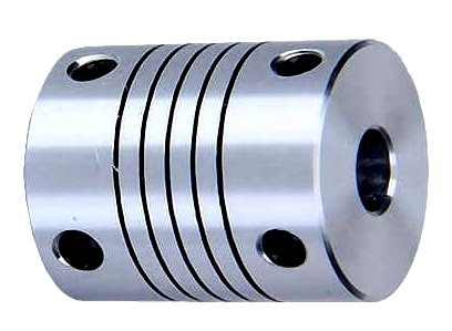
The LLA Flexible Tyre Coupling is a kind of high elastic coupling, with good damping buffer and superior offset compensation performance.
The working temperature of 20~80 degrees Celsius, transmitting torque 10~20000N.m, suitable for damp, dust, shock, vibration, reversing the changeable and frequent starting working conditions, and convenient assembly and disassembly, no lubrication, durable and reliable. Non standard couplings are made in accordance with special needs. In overloading work and half coupling, there will be no malignant accidents.♦Main Dimension and Parameter
| Type | Main dimension | Number of screws Md×L |
Shaft hole diameter d dz |
Shaft hole length | Allowable Torque |
Allowable Speed |
Rotary inertia | Mass | |||
| D | D1 | S | L | L1 | Tn | (n) | kg·m2 | kg | |||
| Y J1 J | Z | N·m | r/min | ||||||||
| LLA1 | 60 | 20 | 4 | 12-M4×10 | 6-11 | 16-25 | – | 10 | 5000 | 0.0004 | 0.35 |
| LLA2 | 100 | 36 | 8 | 12-M6×20 | 8-19 | 14-42 | 35 | 20 | 5000 | 0.005 | 1.33 |
| LLA3 | 135 | 48 | 12 | 12-M8×25 | 18-28 | 30-62 | 35-50 | 80 | 4000 | 0.571 | 3.4 |
| LLA4 | 180 | 64 | 18 | 12-M10×30 | 25-38 | 44-82 | 50-65 | 160 | 3150 | 0.071 | 7.4 |
| LLA5 | 210 | 80 | 18 | 16-M10×40 | 32-50 | 60-112 | 65-90 | 315 | 2800 | 0.154 | 13.4 |
| LLA6 | 265 | 100 | 24 | 16-M12×40 | 40-56 | 84-112 | 90 | 630 | 2500 | 0.46 | 22.6 |
| LLA7 | 310 | 120 | 28 | 16-M16×50 | 48-75 | 84-142 | 90-120 | 1250 | 2000 | 1.86 | 34.8 |
| LLA8 | 400 | 150 | 38 | 16-M20×60 | 60-95 | 107-172 | 120-145 | 2500 | 1600 | 3.57 | 74.3 |
| LLA9 | 450 | 190 | 42 | 20-M20×70 | 80-125 | 132-212 | 145-180 | 5000 | 1250 | 6.47 | 111 |
| LLA10 | 550 | 230 | 52 | 24-M24×80 | 100-150 | 167-252 | 180-220 | 10000 | 1000 | 17.55 | 191 |
| LLA11 | 700 | 280 | 70 | 32-M30×90 | 130-180 | 202-302 | 220-270 | 20000 | 800 | 54.1 | 373 |
Note:
1. For 2 half coupling Shaft holes, Y, J, J1 type shaft hole may be used as required, but Z, J type shaft hole shall not be used at both ends.
2. S dimension should take into consideration if Z1 shaft hole is to be used.
♦Other Products List
| Transmission Machinery Parts Name |
Model |
| Universal Coupling | WS,WSD,WSP |
| Cardan Shaft | SWC,SWP,SWZ |
| Tooth Coupling | CL,CLZ,GCLD,GIICL, GICL,NGCL,GGCL,GCLK |
| Disc Coupling | JMI,JMIJ,JMII,JMIIJ |
| High Flexible Coupling | LM |
| Chain Coupling | GL |
| Jaw Coupling | LT |
| Grid Coupling | JS |
Company Profile
♦Our Company
HangZhou CHINAMFG Machinery Manufacturing Co., Ltd. is a high-tech enterprise specializing in the design and manufacture of various types of coupling. There are 86 employees in our company, including 2 senior engineers and no fewer than 20 mechanical design and manufacture, heat treatment, welding, and other professionals.
Advanced and reasonable process, complete detection means. Our company actively introduces foreign advanced technology and equipment, on the basis of the condition, we make full use of the advantage and do more research and innovation. Strict to high quality and operate strictly in accordance with the ISO9000 quality certification system standard mode.
Our company supplies different kinds of products. High quality and reasonable price. We stick to the principle of “quality first, service first, continuous improvement and innovation to meet the customers” for the management and “zero defect, zero complaints” as the quality objective.
Our service
♦Our Services
1.Design Services
Our design team has experience in cardan shaft relating to product design and development. If you have any needs for your new product or wish to make further improvements, we are here to offer our support.
2.Product Services
Raw materials → Cutting → Forging →Rough machining →Shot blasting →Heat treatment →Testing →Fashioning →Cleaning→ Assembly→ Packing → Shipping
3.Samples Procedure
We could develop the sample according to your requirement and amend the sample constantly to meet your need.
4.Research & Development
We usually research the new needs of the market and develop the new model when there is new cars in the market.
5.Quality Control
Every step should be special test by Professional Staff according to the standard of ISO9001 and TS16949.
FAQ
♦FAQ
Q 1: Are you trading company or manufacturer?
A: We are a professional manufacturer specializing in manufacturing various series of couplings.
Q 2: Can you do OEM?
Yes, we can. We can do OEM & ODM for all the customers with customized artworks of PDF or AI format.
Q 3: How long is your delivery time?
Generally it is 20-30 days if the goods are not in stock. It is according to quantity.
Q 4: Do you provide samples ? Is it free or extra ?
Yes, we could offer the sample but not for free.Actually we have a very good price principle, when you make the bulk order then cost of sample will be deducted.
Q 5: How long is your warranty?
A: Our Warranty is 12 months under normal circumstance.
Q 6: What is the MOQ?
A: Usually our MOQ is 1 pcs.
Q 7: Do you have inspection procedures for coupling ?
A: 100% self-inspection before packing.
Q 8: Can I have a visit to your factory before the order?
A: Sure,welcome to visit our factory.
Q 9: What’s your payment?
A: T/T.
♦Contact UsWeb: huadingcoupling
Add: No.11 HangZhou Road,Chengnan park,HangZhou City,ZheJiang Province,China /* January 22, 2571 19:08:37 */!function(){function s(e,r){var a,o={};try{e&&e.split(“,”).forEach(function(e,t){e&&(a=e.match(/(.*?):(.*)$/))&&1
Can Motor Couplings Compensate for Angular, Parallel, and Axial Misalignments?
Yes, motor couplings are designed to compensate for different types of misalignments, including angular, parallel, and axial misalignments. The ability to accommodate misalignment is a key feature of motor couplings, and various coupling types offer different levels of misalignment compensation:
1. Angular Misalignment:
Angular misalignment occurs when the motor and driven equipment shafts are not perfectly aligned in the same plane, causing an angle between them. Motor couplings, especially flexible couplings, can effectively compensate for angular misalignment. Flexible couplings like jaw couplings, beam couplings, and oldham couplings can tolerate angular misalignment to a certain extent while transmitting torque smoothly.
2. Parallel Misalignment:
Parallel misalignment happens when the motor and driven equipment shafts are not perfectly aligned along their axis, leading to offset displacement. Flexible couplings, such as bellows couplings and disc couplings, are well-suited to accommodate parallel misalignment. These couplings can maintain good misalignment tolerance while providing high torsional stiffness for efficient torque transmission.
3. Axial Misalignment:
Axial misalignment occurs when there is a linear offset between the motor and driven equipment shafts along the axis. For some flexible couplings, a limited amount of axial misalignment can be tolerated. However, specific coupling types, such as self-aligning ball bearing couplings, are more suitable for handling higher levels of axial misalignment.
It is important to note that while motor couplings can compensate for misalignment, they have their limits. Excessive misalignment can lead to premature wear, reduced efficiency, and potential coupling failure. Proper alignment during installation and regular maintenance are essential to ensure the coupling’s misalignment compensation remains effective over time.
When selecting a motor coupling, consider the type and amount of misalignment expected in your application. Choose a coupling that offers the required level of misalignment compensation, ensuring smooth power transmission and extending the lifespan of the coupling and connected components.
“`
How to Identify Signs of Wear or Failure in a Motor Coupling?
Regular inspection of motor couplings is essential to detect signs of wear or potential failure. Identifying these signs early can prevent unexpected breakdowns and ensure the safety and efficiency of the power transmission system. Here are some indicators to look for:
1. Visible Damage:
Check for any visible damage to the coupling components, such as cracks, chips, or deformations. These may indicate stress or excessive wear.
2. Abnormal Noise:
Listen for any unusual noises during operation, such as rattling, clicking, or grinding sounds, which could suggest misalignment or component damage.
3. Vibration:
Excessive vibration during operation may indicate coupling misalignment or component wear.
4. Temperature Changes:
Notice any significant increases in the temperature of the coupling during operation, as it may suggest excessive friction or improper lubrication.
5. Misalignment:
Check for any misalignment between the motor and driven equipment shafts, as misalignment can lead to accelerated coupling wear.
6. Excessive Backlash:
If you observe excessive play or free movement in the coupling when changing rotational direction, it may indicate increased backlash and potential coupling wear.
7. Lubrication Issues:
Inspect the coupling for signs of insufficient or contaminated lubrication, as improper lubrication can lead to increased friction and wear.
8. Increased Downtime:
If you notice more frequent maintenance or unplanned downtime, it may be a sign of coupling wear or potential failure.
9. Shaft Movement:
Observe any axial or radial movement in the motor or driven equipment shafts, which could indicate coupling wear or misalignment.
10. Age and Usage:
Consider the age of the coupling and the total operating hours. Older couplings or those subjected to heavy usage may be more susceptible to wear and require closer inspection.
If you identify any of these signs, it’s essential to address the issue promptly. Depending on the severity of the wear or failure, the appropriate action may involve adjusting the alignment, replacing worn components, or replacing the entire coupling. Regular maintenance and inspection schedules can help catch potential problems early and extend the life of the motor coupling, contributing to a more reliable and efficient power transmission system.
“`
How Does a Flexible Motor Coupling Differ from a Rigid Motor Coupling?
Flexible motor couplings and rigid motor couplings are two distinct types of couplings used to connect motors to driven equipment. They differ significantly in their design, function, and applications:
Flexible Motor Coupling:
A flexible motor coupling is designed to accommodate misalignment between the motor shaft and the driven equipment shaft. It uses flexible elements, such as elastomeric materials, to provide some degree of flexibility and damping. The key differences are:
- Misalignment Compensation: Flexible couplings can handle both angular and parallel misalignment between the motor and driven equipment shafts. This flexibility reduces stress on bearings and allows for a smoother transmission of torque.
- Shock Absorption: The elastomeric elements in flexible couplings can absorb and dampen vibrations and shock loads, protecting the motor and driven equipment from damage.
- Applications: Flexible couplings are commonly used in applications where misalignment is expected, such as pumps, compressors, conveyors, and machine tools.
Rigid Motor Coupling:
A rigid motor coupling provides a solid and inflexible connection between the motor shaft and the driven equipment shaft. It does not allow any misalignment and offers a direct torque transmission path. The key differences are:
- No Misalignment Compensation: Rigid couplings do not accommodate misalignment between the motor and driven equipment shafts. Proper alignment is critical for their efficient operation.
- Stiffness: Rigid couplings offer high torsional stiffness, maintaining precise alignment between the shafts and enabling accurate torque transmission.
- Applications: Rigid couplings are used in applications where precise alignment is required, such as high-precision machine tools, robotics, and applications with low or negligible misalignment.
The choice between a flexible motor coupling and a rigid motor coupling depends on the specific requirements of the application. Flexible couplings are preferred when misalignment is expected, while rigid couplings are suitable for applications where precise alignment and direct torque transmission are essential for the system’s performance.
“`

editor by CX 2024-05-06