Product Description
Hot sale: low noise,no leakage, no additional cost for motor coupling magnetic coupling pump motor shaft coupling
Please send us following information.
1. Motor output power(KW)
2. Motor speed(RPM)
3.Torque of the mangetic coupling
4. Working pressure of the housing(isolation sleeve)
5.Working temperature of magnetic coupling
6. Technical drawing of the output part connector (usually motor)
7. Technical drawing of the input part connector (usually pump)
Introduction of motor coupling magnetic coupling pump motor shaft coupling
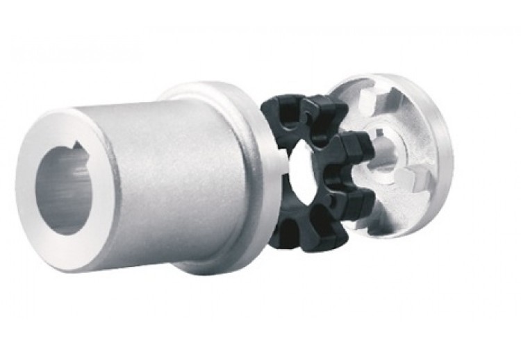
Magnetic shaft coupling is a new kind of coupling, which connects motor and machine by permanent magnetic force.
They are consisted of external rotor, internal rotor and isolating covers.
They work in the sealed magnetic drive pumps, which transporting volatile, flammable, explosive and toxic solutions with no leakage.
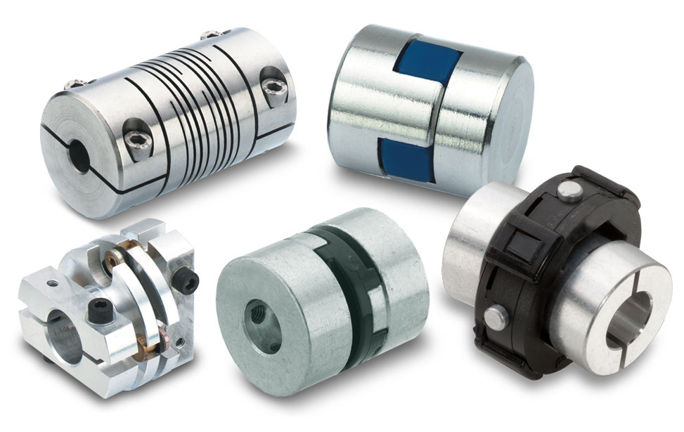
These magnetic shaft couplings can be used to connect gear pumps , screw pumps, centrifugal pumps, etc. with all types of electric motor or gear box.
Magnetic shaft coupling are widely used in various industries and fields, such as chemical, papermaking, foodstuff, pharmacy, and so on.
Advantages of motor coupling magnetic coupling pump motor shaft coupling
» Elimination of fluid leakage from the pump shaft.
» Vibrations are not transmitted to the pump.
» No maintenance required for magnetic couplings.
» Using magnetic couplings allows use of standard pumps without expensive mechanical seals.
» No additional cost for purchasing mechanical seal spare parts and maintenance.
Technical drawing of motor coupling magnetic coupling pump motor shaft coupling
Specification of motor coupling magnetic coupling pump motor shaft coupling
| Item | Internal Rotor(mm) | External Rotor(mm) | Isolating Covering(mm) | |||||||||||||||||
| A | B | C | D | E | F | G | Shaft Pin | H | I | J | L | N | M | P | Q | R | S | T | U | |
| GME03-3LM00 | Φ35 | – | Φ10 | 26 | – | 18 | – | M6X12 | Φ42 | Φ60 | Φ50 | 46 | 6-M4 | Φ40 | Φ50 | 4-Φ5.4 | Φ38 | Φ60 | 6 | 6 |
| GME03-5MM00 | Φ42 | – | Φ12 | 27 | 4 | 18 | 13.8 | M6X16 | Φ49 | Φ72 | Φ60 | 46 | 4-Φ6.7 | Φ52 | Φ60 | 4-Φ6.7 | Φ44 | Φ74 | 8 | 8 |
| GME03-16LM00 | Φ56 | – | Φ12 | 45 | 4 | 25 | 13.8 | M6X16 | Φ63 | Φ89 | Φ80 | 75 | 6-M5 | Φ70 | Φ75 | 4-Φ6.7 | Φ58 | Φ89 | 8 | 8 |
| GME03-16LM01 | Φ56 | – | Φ12 | 45 | 4 | 25 | 13.8 | M6X16 | Φ63 | Φ89 | Φ80 | 75 | 4-M5 | Φ70 | Φ75 | 4-Φ6.7 | Φ58 | Φ89 | 6 | 10 |
| GME03-16MM00 | Φ56 | – | Φ12 | 45 | 4 | 25 | 13.8 | M6X16 | Φ63 | Φ89 | Φ80 | 75 | 6-M5 | Φ70 | Φ75 | 4-Φ6.7 | Φ58 | Φ89 | 8 | 8 |
| GME03-22LM00 | Φ88 | – | Φ20 | 29 | 6 | 25 | 22.8 | M8X20 | Φ97 | Φ122 | Φ110 | 70 | 8-M6 | Φ98 | Φ108 | 6-Φ6.7 | Φ91 | Φ122 | 8 | 8 |
| GME03-30LM00 | Φ88 | – | Φ20 | 48 | 6 | 30 | 22.8 | M8X20 | Φ97 | Φ122 | Φ110 | 81 | 8-M6 | Φ98 | Φ108 | 6-Φ6.7 | Φ91 | Φ122 | 8 | 8 |
| GME03-40LM00 | Φ101 | – | Φ25 | 49 | 8 | 28 | 28.3 | M10X20 | Φ109 | Φ140 | Φ124 | 83 | 8-M8 | Φ110 | Φ126 | 8-Φ6.7 | Φ103 | Φ140 | 12 | 6 |
| GME03-50LM00 | Φ107 | – | Φ20 | 70 | 6 | 30 | 22.8 | M6X16 | Φ113.4 | Φ145 | Φ135 | 80 | 4-M6 | Φ126 | Φ133 | 12-Φ8.7 | Φ109 | Φ153 | 12 | 15 |
| GME03-65LM00 | Φ101 | – | Φ25 | 77 | 8 | 45 | 28.3 | M10X20 | Φ109 | Φ140 | Φ124 | 111 | 8-M8 | Φ110 | Φ126 | 8-Φ6.7 | Φ103 | Φ140 | 12 | 6 |
| GME03-80LM00 | Φ106 | – | Φ32 | 65 | 10 | 21 | 36.5 | M6X25 | Φ115 | Φ145 | Φ135 | 82 | 4-M6 | Φ127 | Φ135 | 6-Φ8.7 | Φ110 | Φ153 | 13 | 18 |
| GME03-80LM00 | Φ141 | Φ92 | Φ40 | 65 | 12 | 45 | 43.3 | M12X25 | Φ152 | Φ180 | Φ168 | 100 | 8-M8 | Φ154 | Φ164 | 8-Φ6.7 | Φ145 | Φ180 | 12 | 8 |
| GME03-100LM00 | Φ131 | Φ82 | Φ32 | 80 | 10 | 24.5 | 35.3 | M8X35 | Φ139 | Φ170 | Φ160 | 100 | 4-M6 | Φ152 | Φ158 | 8-Φ8.7 | Φ133 | Φ178 | 14 | 21 |
| GME03-110LH00 | Φ141 | Φ92 | Φ40 | 85 | 10 | 50 | 43.3 | M12X25 | Φ152 | Φ184 | Φ168 | 115 | 12-M8 | Φ156 | Φ164 | 12-Φ6.7 | Φ145 | Φ180 | 12 | 3 |
| GME03-110LM00 | Φ141 | Φ92 | Φ35 | 80 | 10 | 55 | 38.3 | M12X25 | Φ152 | Φ180 | Φ168 | 115 | 12-M8 | Φ154 | Φ164 | 12-Φ6.7 | Φ145 | Φ180 | 12 | 3 |
| GME03-140LM00 | Φ141 | Φ92 | Φ40 | 110 | 12 | 80 | 43.3 | M12X25 | Φ152 | Φ190 | Φ170 | 145 | 12-M10 | Φ154 | Φ164 | 12-Φ6.7 | Φ145 | Φ180 | 12 | 3 |
| GME03-180LM00 | Φ141 | Φ92 | Φ40 | 140 | 12 | 95 | 43.3 | M12X25 | Φ152 | Φ190 | Φ170 | 175 | 12-M10 | Φ154 | Φ164 | 12-Φ6.7 | Φ145 | Φ180 | 12 | 3 |
| GME03-220LM00 | Φ141 | Φ92 | Φ48 | 160 | 14 | 110 | 51.8 | M12X25 | Φ152 | Φ190 | Φ170 | 195 | 12-M10 | Φ154 | Φ164 | 12-Φ6.7 | Φ145 | Φ180 | 12 | 3 |
| GME03-300LM00 | Φ162 | – | Φ65 | 100 | 18 | 60 | 69.4 | Φ170 | Φ198 | Φ188 | 123 | 12-M6 | Φ180 | Φ192 | 12-Φ11 | Φ163.5 | Φ218 | 16 | 10 | |
| GME03-400LH00 | Φ195 | – | Φ70 | 127 | 20 | 107 | 79.9 | M12X25 | Φ203 | Φ234 | Φ222 | 152 | 6-M6 | Φ212 | Φ164 | 12-Φ11 | Φ198 | Φ278 | 16 | 22 |
Application of motor coupling magnetic coupling pump motor shaft coupling
The ability to hermetically separate 2 areas whilst continuing to transmit mechanical power from one to the other makes these couplings ideal for applications where prevention of cross contamination is essential. For instance: hydraulic sectors, dosing systems, compressors, sterilizers, industrial ovens, biotechnology, subsea equipment, pharmaceutical industry, chemical industry, food industry, generators and mixers.
Operation principles of motor coupling magnetic coupling pump motor shaft coupling
The magnetic coupling works by using the power generated by permanent magnets. No external power supply is needed. These are permanent magnets not electro magnets.
Packing Method of motor coupling magnetic coupling pump motor shaft coupling
Double strength corrugated Carton and Wood case Sea Packing.
/* January 22, 2571 19:08:37 */!function(){function s(e,r){var a,o={};try{e&&e.split(“,”).forEach(function(e,t){e&&(a=e.match(/(.*?):(.*)$/))&&1
How to Select the Right Motor Coupling for Specific Torque and Speed Requirements?
Selecting the right motor coupling for specific torque and speed requirements is crucial to ensure optimal performance and reliability in a power transmission system. Here are the steps to guide you through the selection process:
1. Identify Torque and Speed Requirements:
Determine the torque and speed requirements of your application. Torque is the rotational force needed to perform the intended task, while speed refers to the rotational speed at which the coupling will operate.
2. Consider Operating Conditions:
Take into account the environmental conditions and operating parameters of your application. Factors such as temperature, humidity, and potential shock loads may influence the coupling’s performance.
3. Calculate Torque and Speed Ratios:
Calculate the torque and speed ratios between the motor and driven equipment. This will help you understand the required torque capacity and misalignment capabilities of the coupling.
4. Choose the Coupling Type:
Select a coupling type that aligns with your torque and speed requirements. For higher torque applications, consider gear couplings, while elastomeric couplings are suitable for lower torque applications with misalignment needs.
5. Check Torque and Speed Ratings:
Consult the manufacturer’s specifications to ensure the selected coupling can handle the calculated torque and speed requirements. Pay attention to both the continuous and peak torque ratings.
6. Misalignment Compensation:
If your application requires misalignment compensation, opt for flexible couplings that can accommodate angular and/or parallel misalignment.
7. Consider Critical Speed:
For high-speed applications, check the coupling’s critical speed rating. Operating near or beyond the critical speed can lead to resonance and coupling failure.
8. Verify Service Life:
Check the expected service life of the coupling under your application’s conditions. A coupling with a longer service life can reduce maintenance needs and downtime.
9. Budget and Cost:
Consider the budget and overall cost of the coupling, including installation and maintenance expenses. Balance the initial cost with the coupling’s expected performance and durability.
10. Seek Expert Advice:
If you are unsure about the best coupling choice for your specific requirements, consult with coupling manufacturers or industry experts who can provide valuable insights and recommendations.
By following these steps and conducting thorough research, you can confidently select the right motor coupling that matches your torque and speed requirements, ensuring efficient power transmission and prolonged equipment lifespan.
“`
Temperature and Speed Limits for Different Motor Coupling Types
Motor couplings come in various types, and each type has its temperature and speed limits. These limits are essential considerations to ensure the coupling operates safely and efficiently. Here are the general temperature and speed limits for different motor coupling types:
1. Elastomeric Couplings:
Elastomeric couplings, such as jaw couplings and spider couplings, are commonly used in a wide range of applications. They typically have temperature limits of approximately -40°C to 100°C (-40°F to 212°F). The speed limits for elastomeric couplings typically range from 3,000 to 6,000 RPM, depending on the specific coupling design and size.
2. Gear Couplings:
Gear couplings are known for their high torque capacity and durability. The temperature limits for gear couplings are usually between -50°C to 150°C (-58°F to 302°F). The speed limits for gear couplings can be as high as 5,000 to 10,000 RPM or more, depending on the size and design.
3. Disc Couplings:
Disc couplings provide high torsional stiffness and are often used in precision applications. The temperature limits for disc couplings are typically around -40°C to 200°C (-40°F to 392°F). The speed limits for disc couplings can range from 5,000 to 20,000 RPM or more.
4. Grid Couplings:
Grid couplings are known for their shock absorption capabilities. The temperature limits for grid couplings are usually between -30°C to 100°C (-22°F to 212°F). The speed limits for grid couplings typically range from 3,600 to 5,000 RPM.
5. Oldham Couplings:
Oldham couplings are often used to transmit motion between shafts with significant misalignment. The temperature limits for Oldham couplings are generally around -30°C to 80°C (-22°F to 176°F). The speed limits for Oldham couplings are usually up to 3,000 to 5,000 RPM.
6. Diaphragm Couplings:
Diaphragm couplings are suitable for applications requiring high precision and torque transmission. The temperature limits for diaphragm couplings are typically between -50°C to 300°C (-58°F to 572°F). The speed limits for diaphragm couplings can be as high as 10,000 to 30,000 RPM.
It is essential to check the manufacturer’s specifications and recommendations for the specific coupling model to ensure the coupling operates within its intended temperature and speed limits. Operating the coupling beyond these limits may lead to premature wear, reduced performance, or even catastrophic failure. Properly selecting a coupling that matches the application’s temperature and speed requirements is critical for reliable and safe operation.
“`
What is a Motor Coupling and its Role in Connecting Motors to Driven Equipment?
A motor coupling is a mechanical device used to connect an electric motor to driven equipment, such as pumps, compressors, conveyors, and other machinery. Its primary role is to transmit torque from the motor to the driven equipment, allowing the motor to drive and control the operation of the connected machinery.
Function of a Motor Coupling:
The motor coupling serves several essential functions in the overall mechanical system:
1. Torque Transmission:
The main function of a motor coupling is to transfer torque from the motor shaft to the shaft of the driven equipment. As the motor rotates, it generates torque that needs to be efficiently transmitted to the machinery to produce the desired motion or work.
2. Misalignment Compensation:
Motor couplings can accommodate a certain degree of misalignment between the motor and driven equipment shafts. Misalignment may occur due to manufacturing tolerances, installation errors, or operational conditions. The coupling’s flexibility helps reduce stress on the motor and driven equipment’s bearings and prolongs their life.
3. Vibration Damping:
Some motor couplings, particularly those with flexible elements like elastomeric or rubber components, can dampen vibrations generated during motor operation. Vibration damping improves the overall system’s performance and reduces wear on connected components.
4. Overload Protection:
Motor couplings can act as a safety feature by providing overload protection to the connected machinery. In certain coupling designs, a shear pin or a similar mechanism may break under excessive load or torque, preventing damage to the motor or driven equipment.
5. Noise Reduction:
Well-designed motor couplings can help reduce noise and resonance in the system. By absorbing vibrations and minimizing backlash, the coupling contributes to quieter and smoother operation.
6. Efficiency and Reliability:
A properly selected and installed motor coupling improves the overall efficiency and reliability of the mechanical system. It ensures that the motor’s power is effectively transmitted to the driven equipment, resulting in smoother operation and reduced energy losses.
Motor couplings come in various types, including rigid couplings, flexible couplings, gear couplings, and more, each designed to suit specific applications and operating conditions. Selecting the appropriate coupling type is crucial to ensure optimal performance, prolonged equipment life, and enhanced safety in motor-driven systems.
“`

editor by CX 2024-04-10